Four Bar Mechanism Tutorial
Problem Statement:
This small project was presented as a set of instructions referencing a set of four pre-modeled linkages. For this tutorial we are supposed to assemble the linkages and create a motion study to model how this system would behave if driven by a motor.
Procedure:
Since the procedure for this project is pre-written, there wasn't any creative freedom related to assembling this. The provided pieces can be seen in Figure 1. With that being said, instructions were not provided for the deliverables of this assignment. For this assignment there were five deliverables, each of which required some sort of analysis related to the motion system. To setup this system, I changed the material properties of each of the linkages to plain carbon steel, applied gravity to the motion study, and found the trace of each quarter of the long bar seen in Figure 2.


Figure 1: Each individual part provided by the assignment.

Figure 2: Assembled mechanism with quarter-bar trace paths.
Deliverables:
The required deliverables are as follows:
a) The maximum value of the motor torque
b) The angle of the crank for which the motor torque is maximum in each cycle
c) The maximum vertical force exerted on Bearing and NewBearing
d) The minimum motor power required to have to move the Crank at a constant angular speed of 600 rpm.
e) Explain the meaning of the negative motor torque values and how they are related to the motion of the mechanism links.
Using the top graph seen in Figure 3, I determined the maximum motor torque to be ~20Nmm in the negative direction. This maximum value corresponds with when the angle of the crank is 180 degrees from its starting position. In other words, when the system has completed half a cycle the torque reaches its maximum. The middle graph in Figure 3 shows the reaction force on the system, with a maximum value of 0.3N downwards. Finally, the bottom graph in Figure 3 shows to power consumption of the mechanism if the motor was to run at 600RPM. The minimum power required would be the maximum value of the graph, which hits 0.04 Watts a little after one half cycle. The negative values for motor torque express the torque felt by the motor in the same direction as the motors motion. This basically means the motor doesn't have to push as much to get the same result when a negative torque is present. Negative torques show up when gravity is assisting the motor in moving the crank.
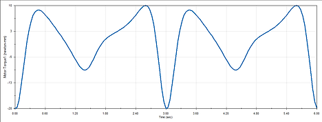
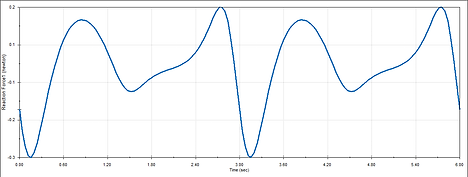

Figure 3: Graphs produced by motion analysis of the mechanism.
Figure 4: The mechanism in motion.
Square Plotter
Problem Statement:
This project was presented as an introduction to linear motion with motors, which is later developed under the 2.5 Degrees of Freedom project. For this project to be successful, a plotter much carry a motor/marker extruder system to trace a 2inx2in square on a piece of paper.
Constraints:
-
Each axis of the plotter must be constructed by a different group/table.
-
The slider must be able to have something mounted on top of it (either extruder or Y-Axis).
Procedure:
To begin with, my group wanted the design to be as simple as possible. We decided the best way to keep it simple and stay productive was to design everything using repeatable squares of of foam board as a base unit. This allowed us to start producing pieces for the final product quickly and in bulk. From there, it was only a matter of deciding how many squares thick each part of the construction would be in order to support each bearing. It was very important for the squares that held the slider to be level with each other, and flush with the bottom base. If we hadn't taken the extra care to make sure that interface was smooth, the motor likely would have jittered or wobbled. Once combined with the other two group's axes, we added a platform on top of the slider to hold the Y-Axis, while our slider and the third group's acted as the X-Axis.

Figure 1: Axis constructed by my group, affectionately labeled
"Shmoovin"


Figure 2: Zoomed out view of the combined three axis plotter,
showcasing the motor controller in the bottom left.
Figure 3: Close up of the reverse side of the plotter. The Ipad was used for spacing purposes.
Figure 4: Full video of the plotter tracing the square.
Bell Analysis


Problem Statement:
Simulate the natural frequencies of some generic bell using Solidworks' mesh simulation package.
Procedure:
Using the provided sketch in Figure 1, I generated a a model in Solidworks and dimensioned it to the size a a moderately sized church bell. After doing a bit of research, I determined that the bell should be made out of a Tin rich Bronze alloy, as seen in Figure 2. From there, it was a simple matter of generating a high quality mesh to cover the volume, as seen in Figure 3. This allows Solidworks to perform discrete calculations on a continuous surface. Fixing the top and analyzing this mesh's natural frequency produces several modes of vibration that this bell would naturally produce, one of which is seen in Figure 4. Using the first three natural modes of vibration, I wrote a simple program to overlay the frequencies together, and dampen the sound. Figure 5 shows the final resulting sound that a bell of this scope would likely produce (sound file may be loud).
Figure 3: Mesh generated around bell. Note the high density to increase quality of results.

Figure 4: Solidworks' interpretation of the bell's first natural frequency mode.
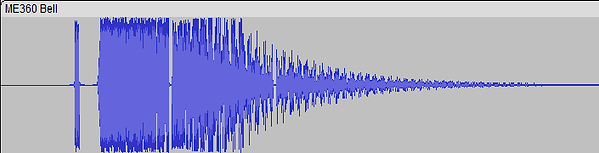
Figure 5: Resulting audio data produced by the MatLab program I wrote to produce the bell's sound (playable on the right).
Figure 2: Bell model with applied material properties.
Bridge Exercise

Problem Statement:
Cars driving down the street are hazardous to crossing pedestrians. Though there is a bridge overpass, it is inconvenient for pedestrians to use, so children still cross the street despite the cars.
Proposed Solution:
The pedestrian's aren't using the foot bridge because it is inconvenient to climb the stairs that allow them to cross. To preserve the money spent to build the bridge, the best solution would be to introduce some obstacle that would prove more inconvenient for the pedestrians to get of than simply using the bridge. Thus, the solution should be to install a chain link fence along the perimeter of the road.
Sketch:
Figure 1: Sketch of bell outlined to be revolved.